By Tom Kuennen, Contributing Editor
Fatigue cracking in bituminous pavements is experienced by the public so often that it is considered just part of driving. Motorists endure it and assume it’s just part of an aging pavement. But the perceptive road manager knows that fatigue cracking in less-deep asphalt pavements is a symptom of distressed base layers, and is indicative of a pavement on its way to failure.
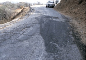
This fatigue cracking usually, but not always, is manifested by so-called alligator cracking. Named for its similarity to the pattern on an alligator’s hide, alligator cracking appears as many sided, sharp-angled pieces, usually less than 12 inches on the longest side. This characteristic alligator or chicken wire pattern appears in later stages of deterioration.
There are three types of fatigue cracking, according to the Federal Highway Administration’s Distress Identification Manual for the Long-Term Pavement Performance Program (to view, search for FHWA-RD-03-031). A concise pocket guide for field use – Distress Identification Guide – also is available from FHWA (download by searching FHWA-RD-05-001).
Neither of these guides explain the why of pavement distresses, instead offering precise identification of distresses in order to provide a common, standard definition for use by pavement managers. In these documents FHWA categorizes types of cracking for asphalt pavements, jointed concrete pavement, and continuously reinforced concrete pavements.
• Low-severity fatigue cracking is an area of cracks with no or only a few connecting cracks; the cracks are not spalled or sealed; pumping of base materials out the cracks is not evident.
• Moderate fatigue cracking is manifested by interconnected cracks forming a complete pattern. The cracks may be slightly spalled and may be sealed, and pumping is not evident.
• High-severity fatigue cracking is an area of moderately or severely spalled interconnected cracks forming a complete pattern; pieces may move when subjected to traffic, cracks may be sealed, and pumping may be evident.
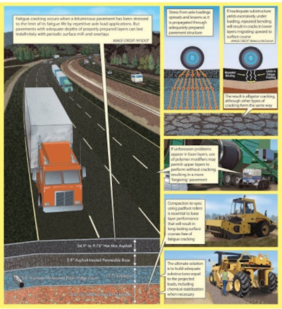
It’s easy to look at fatigue cracking in thinner pavements and assume it’s a surface problem, but subsurface investigation will find fatigue cracking is bottom-up cracking, in which stresses propagated to asphalt pavement foundations cause cracks in inadequate base layers. As the asphalt pavement structure flexes under loads, these foundation cracks work their way upward through the pavement. Typically they are found in pavements subjected to repeated traffic loadings, like wheel paths, and can be a series of interconnected cracks.
“[Fatigue cracking] generally occurs when the pavement has been stressed to the limit of its fatigue life by repetitive axle load applications,” according to Hot Mix Asphalt Materials, Mixture Design and Construction, published by the National Asphalt Pavement Association’s Research and Education Foundation. “Fatigue cracking is often associated with loads that are too heavy for the pavement structure or more repetitions of a given load than provided for in design.”
Poorly drained bases exacerbate the problem. As the cracks in the base layers work their way upward, capillary action will draw water from undrained bases up into the pavement, where it damages the pavement structure through reflection cracking, cracks along longitudinal joints, cracks in wheel paths, alligatoring, raveling and potholes.
“The problem is often made worse by inadequate pavement drainage, which contributes to this distress by allowing the pavement layers to become saturated and lose strength,” NAPA says. “The HMA layers experience high strains when the underlying layers are weakened by excess moisture and fail prematurely in fatigue. Fatigue cracking also is often caused by repetitive passes with overweight trucks and/or inadequate pavement thickness due to poor quality control during construction.”
New Look at Top-Down Cracking
Not all fatigue cracking is bottom-up; in thick pavements, cracks may start from the top of the pavement in areas of high localized tensile stresses.
“[L]oad-related top-down fatigue cracking – i.e., cracking that initiates at the surface of the pavement and propagates downward – commonly occurs in hot mix asphalt (HMA) pavement,” say Hong Joon Park and Y. Richard Kim, Ph.D., P.E., North Carolina State University-Raleigh, in their 2013 Transportation Research Board paper, Investigation into the 


“Top-down Top-cracking cannot be explained by the traditional fatigue mechanisms that are used to explain load-associated fatigue cracking that initiates at the bottom of the pavement,” they say.
Their literature review quotes a field study that found top-down cracking occurs in pavement layers that typically are more than 6.3 inches thick. And stiffness of asphalt does not seem to be an issue, the study says; in sections that exhibit top-down cracking, falling weight deflectometer (FWD) data do not show as much reduction in structural stiffness as do sections that exhibit full-depth cracking.
The researchers used two different methods to study the structural differences between bottom-up and top-down fatigue cracking, the viscoelastic continuum damage finite element program (VECD-FEP) to calculate stresses and strains in a pavement as microcracks initiate and propagate, and the AREA parameter that is determined from falling weight deflectometer deflections, and pavement thicknesses.
 No patching can cure severe fatigue cracking, which indicates profound base failure; road ultimately was in-place foam-recycled with thin overlay.
In the lab they used a mechanistic approach that uses cores to investigate crack initiation locations and the propensity of asphalt pavements to exhibit top-down cracking. They concluded the FWD-based in situ method will allow pavement engineers to identify the existence and likelihood of top-down cracking. “This simplified method will not only reduce the time and cost involved for the engineer to verify the structural soundness of the pavement, but will also lead to selecting the optimal maintenance treatment,” Park and Kim conclude.
Virginia Fixes Fatigue Cracking
Roads can be constructed to resist fatigue cracking. But as fatigue cracking will appear in existing pavements, a road manager’s first challenge will be to rebuild the existing pavement to preclude future bottom-up fatigue cracking.
In 2011 the Virginia Department of Transportation rebuilt a section of I-81 in the shadow of the Blue Ridge Mountains. Fatigue cracking, caused by years of heavy traffic loads, had deteriorated the pavement structure from bottom to top. While the symptoms of this deterioration could have been addressed by mill-and-overlay, VDOT says, the underlying condition would have remained, and the cause of this extensive wear could only be remedied by reworking all the material down to the subgrade.
This section of I-81 was constructed in the late 1960s. VDOT routinely maintained the surface asphalt with periodic patching and overlays. However, the original foundation of compacted stone aggregate and soil had weakened to the point it no longer provided a stable base for the overlying asphalt layers.
“Unless the foundation is repaired, simply repaving the road surface is a temporary improvement,” VDOT says in a public outreach statement. “If VDOT were to do nothing to this section of road, the pavement would crack more. Pieces up to the size of a golf ball could come out of the road. The fatigue cracks also allow a direct path for water to seep down to the pavement foundation. The water saturates the subgrade, further reducing its load-carrying capacity. This condition can lead to deep rutting within the wheel paths that can affect skid resistance and even steering ability.”
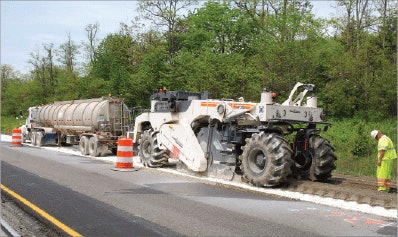
 Revealed, failed base of Virginia I-81 is stabilized in situ using hydrated lime kiln dust; existing asphalt courses above were foam-recycled at portable cold mix plant adjacent to project and placed over this stabilized base.
“This section of I-81 is 43 years old,” says Chaz B. Weaver, P.E., district materials engineer, VDOT Staunton District Materials Section. “It was really beaten up. It had gotten more truck traffic, and lasted longer, than it was originally designed for. We had gotten to a point where our maintenance cycles were three, maybe four years long, with patching in-between. It’s very, very expensive to come out every four years, while we are looking for a 10- to 12-year cycle for a surface fix.
“Cores evaluation and pavement analysis with the falling weight deflectometer indicated that the base layer – about 24 to 26 inches down – had failed,” Weaver says. “We needed a process that could go in very deep, fix the entire pavement structure, and get out very quickly. With specialized machinery and the recycling process we can do that efficiently, and accelerate construction as much as possible.”
The existing subgrade had been built on top of impervious, plastic clayey soil, and did not have drains built alongside. “There were no underdrains or subgrade drainage in the design,” Weaver says. “The pavement structure was like a bathtub. Water got in and stayed in. We actually had some pumping of water and fines coming up through the surface. Trucks have only gotten heavier in the 43 years since the pavement was constructed and we’re up to 30 percent trucks.”
Roanoke-based Lanford Brothers Co. was prime contractor for the I-81 In-Place Pavement Recycling Project in Augusta County south of Staunton. As part of the $7.6 million project, Lanford Brothers rehabilitated and paved a 3.7-mile section of southbound I-81 in Virginia’s Shenandoah Valley that had experienced deterioration in the highway’s subbase.
After rebuilding shoulders to accommodate work zone traffic, Lanford first milled the top 10 inches of asphalt from the right-hand “truck” lane and brought it to a Wirtgen KMA 220 portable cold mix plant just off the Interstate, adjacent to the work zone. There it was foam-recycled for immediate placement on I-81 as a flexible base course.
In the meantime, the revealed, existing subgrade – which had deteriorated to the point of causing damage to the friction course – was stabilized by subcontractor Slurry Pavers Inc. using 5 percent lime kiln dust [Calciment, a reclaimed industrial byproduct] to a depth of 12 inches and compacted in-place with padfoot and smooth drum rollers.
The recycled foamed asphalt mix from the portable plant then was used to pave a new flexible base course over the restored subgrade to 6 inches compacted depth, later to be topped with a 4-inch intermediate course of conventional hot mix asphalt (HMA) and a 2-inch friction course of stone-matrix asphalt (SMA).
In the second phase of the project, subcontractor Reclamation Inc. of West Hurley, N.Y., performed in-place foam recycling in the left-hand passing lane. For this work the top 2 inches of pavement was milled off, followed by cold in-place recycling (CIR) of the next 5 inches. The foamed asphalt-stabilized base layer then was compacted using two Hamm smooth-drum vibratory rollers and one pneumatic (rubber-tire) roller. It was then topped with a 2-inch HMA intermediate course and a 2-inch friction course of SMA.
MEPDG: Building Not to Fail
As Virginia I-81 showed, there is no real way to fix bottom-up fatigue cracking without digging out the base, rebuilding, stabilizing and replacing the pavement structure.
The new Mechanistic-Empirical Pavement Design Guide (MEPDG) and associated software – now in various stages of adoption throughout the state DOTs –provides a state-of-practice mechanistic-empirical highway pavement design methodology based on actual experience from the real world, translated to a design program, and in the near future will be the first place to which agencies will go for designing fatigue-resistant pavements.
The MEPDG methodology is based on pavement responses computed using detailed traffic loading, material properties, and environmental and climatic data. The responses are used to predict incremental damage to the pavement structure over time.
“Design is an iterative process using analysis results based on trial designs postulated by the designer,” according to the 2010 report, Mechanistic-Empirical Pavement Design Guide Implementation, by R.L. Baus and N.R. Stires. “A trial design is analyzed for adequacy against user input performance criteria. These criteria are established by policy decisions and represent the amount of distress or roughness that would trigger some major rehabilitation or reconstruction activity.”
The output of the computer software is a prediction of distresses and smoothness against set reliability values. If the predictions do not meet the desired performance criteria at the given reliability, the trial design is revised and the evaluation is repeated.
“The MEPDG method provides for three hierarchical levels of design inputs to allow the designer to match the quality and level of detail of the design inputs to the level of importance of the project (or to best utilize available input data),” Baus and Stires say. “In addition to inputs required to quantify a trial pavement structure, the MEPDG requires over 100 inputs to characterize traffic loading, material properties and environmental factors.”
The MEPDG will provide pavement structure details, but it will be up to the contractor to build the road right. The subgrade soil material under most prepared bases will need to be compacted, as well as the base itself, because it acts as a platform on which the base is placed. Each needs to be compacted at or near its optimum moisture content, neither too dry nor too wet, although too dry is better than too wet for any compaction.
But if the base is not within about 2 percent of its optimum moisture content, it will never be densified or compacted to the point where it has the strength and durability to carry the prepared layers and pavement above.
That’s critical because nearly every road agency will have a spec and conduct tests to determine what the moisture content should be for the construction. But agency staff reductions and loss of qualified field personnel can result in supervisory oversights, and base problems permanently built into the completed structure, not to reveal themselves until years later.
Bases for flexible HMA and portland cement concrete roads differ greatly. The base beneath a rigid PCC slab is there to provide profile, as the loading from traffic is carried by the slab. Not much force is transmitted beneath the slab.
For the HMA pavement, traffic loads are transmitted by tires through the pavement to the underlying base. The greatest concentration of pressure will be at the surface, and then distributed in a bell-shape to depths below.
Crushed aggregate base gets its strength from the frictional interlock of the stone. Point loading tends not to dissipate so far, and deflection of the base is not as great, so the base serves excellently for profile. But when cohesive, sticky materials like clays comprise the base, stabilization with asphalt emulsion, lime, cement or fly ash, or foamed asphalt is indicated, to counter the effect of the material’s adverse reaction to the presence of water, when it can expand and destroy a pavement.
The more cohesive the soils are, the more likely they will be to react adversely in the presence of moisture. The stabilizing agent effectively seals or waterproofs the base to keep the moisture out and make it more stable, thus providing a superior foundation to resist bottom-up fatigue cracking.


