


Geosynthetics Speed Construction While Enhancing Pavement Performance
 Geocomposites promote drainage in pavement structures, from moisture moving both upward and downward in a base; here, geocomposite layers connect to longitudinal side drains to expedite discharge. (Photo credit: Tensar)
Geosynthetics comprise a family of value-added products that allows highways, roads and bridges to be built faster, cheaper and longer lasting.
Some geosynthetics enhance pavement longevity by separating good materials from bad. Some promote water flow from pavement structures as they facilitate drainage.
And while most geosynthetics are planar or sheet-like in format, three-dimensional geogrids add structural strength to a road section, permitting reduced depths of aggregate bases and bituminous lifts.
Family of Geosynthetics
ASTM (2006) D 4439 defines a geosynthetic as a “planar product manufactured from a polymeric material used with soil, rock, earth or other geotechnical-related material as an integral part of a civil engineering project, structure, or system.”
“Geosynthetics are man-made polymeric materials used for geotechnical application,” says the California DOT in its Caltrans Geotechnical Manual. “They are used in lieu of conventional materials and often are more cost effective with equal or improved engineering performance.”
“Geosynthetics are materials that are incorporated into layers of rock or soil that provide separation of good material from lesser material,” said Aaron Schlessinger, E.I.T., southwest region manager for Tensar International Corp. “Others provide reinforcement while still others enhance drainage.”
There are four different types of geosynthetics:
• Geotextiles, are either woven or nonwoven, and used in civil engineering projects. Their mission is to prevent soils from migrating into drainage aggregate bases or pipes, while maintaining water flow through the system. They are used for filtration, drainage, separation, reinforcement, and as a fluid barrier. A subset of geotextiles are paving fabrics used between pavement lifts.
• Geogrids are formed by a network of tensile elements with openings of sufficient size to allow interlock with the surrounding fill materials. They provide reinforcement, with geogrids oriented such that their principal strength is in one direction (uniaxial), or in both directions (biaxial geogrids), or in three directions (triaxial).


• Geocomposites are a combination of two or more geosynthetic materials, such as geotextiles with a core, and are used to enhance drainage, for example as prefabricated longitudinal edge drains or a layer feeding those drains.
• Geomembranes are a single, solid sheet of geosynthetic material, used in construction as an impermeable barrier above structural backfill.
Use of a geosynthetic for separation prevents intermixing between two adjacent dissimilar materials, so that the integrity of materials on both sides of the geosynthetic remains intact, according to Caltrans. This keeps weak subgrade soils from pumping through overlying fill, or prevents contamination of select fill by intrusion into the subgrade. “This may allow stable construction over soils that may otherwise require expensive ground improvement technologies,” Caltrans says.
Geosynthetics can add value to the construction sequence by saving material costs associated with working surfaces, expediting construction schedules, and providing a permanent working surface that yields a smooth riding surface, Tensar says. Their added cost, though, must be balanced by savings in material and labor, along with long-term benefits in increased pavement durability. Finding the right combination is the challenge of the civil engineer.
Geotextiles Separate Layers
Whether woven or nonwoven, the “planar” geotextile (vs two- or three-dimensional geogrid) must allow migration of water while keeping dissimilar materials apart. They perform according to their apparent opening size – or AOS – which must be smaller than the smallest size particle to be retained, and still allow for the flow of water through the geotextile material.
Geotextiles (woven and nonwoven) are used as separators and filters to prevent soils from migrating into drainage aggregate, granular bases or pipes, while maintaining water flow through the system, according to the Iowa DOT. “Geotextiles are also used below riprap and other armor materials to prevent erosion of the soils from the stream bank,” Iowa DOT says.
“The geotextile should be selected to prevent the migration of fines based on the AOS criteria,” Iowa says. “In addition, geogrids may also be used as a separator to prevent the migration of granular materials (aggregate) into fine-grained, soft subgrade soils. However, this application will not prevent the migration of fines from the subgrade soil into the aggregate.”
Even as separators, nonwoven needle-punched geotextiles and geocomposites provide drainage by allowing water to drain from or through low permeability soils. “In some cases, the nonwoven geotextile will need to be thick enough to allow the flow of water through the geotextile material itself,” Iowa DOT says. “In other cases, the geotextile must transmit enough flow through to the underlying core material (such as wick drain or drainage board). Thus, the geotextile will need to be sized to have enough flow rate or transmissivity to achieve the required drainage.”
Paving Fabrics and WMA
Geosynthetics are used within asphalt pavement structures as well as below them. “Geosynthetic pavement interlayers [also called paving fabrics] provide numerous benefits to a pavement system,” say Bradley J. Putman and William P. Bolger, Clemson University, in their 2014 Transportation Research Board paper, Laboratory Investigation of the Effect of Compaction Temperature on Geosynthetic Pavement Interlayers Made with Warm Mix Asphalt Overlays.
“When utilized properly, these interlayers can prevent water from infiltrating a roadway base and also assist in absorbing pavement stresses, thus extending the life of a pavement,” Putman and Bolger say. “Geosynthetic pavement interlayers lead to an increase in the performance of a pavement overlay by retarding fatigue and reflective cracking.”
Typically the most common geosynthetic interlayer system consists of the existing base pavement, tack coat, nonwoven geotextile paving fabric, and an asphalt overlay.
One of the most important factors affecting the performance of geosynthetic interlayers is the bond that is established between the old pavement and the new overlay, they say.
“This interfacial bond is directly affected by the type and amount of tack coat,” Putnam and Bolger write. “Paving fabric interlayer systems are typically constructed beneath hot mix asphalt overlays having a minimum thickness of 1.5 in. to ensure enough heat to draw the asphalt tack coat up into the paving fabric.
It’s generally recommended that the overlay temperature does not exceed 325 deg F to prevent thermal damage to the paving fabric, the authors say, adding it’s also recommended that the overlay temperature is not below 250 deg F because lower temperatures may not generate sufficient heat to warm up the tack coat enough to saturate the overlying paving fabric to create a well-bonded interlayer that will be a moisture barrier and provide stress-absorbing benefits.
In view of the increasing use of warm mix asphalt, which may not reach those temperatures, Putnam and Bolger evaluated the feasibility of using paving fabric interlayers with the lower compaction temperatures encountered with WMA overlays. Using Petromat 4598 they studied paving fabric interlayers made with four different tack coat binder grades, and asphalt overlays ranging from 200 to 300 deg F using a melt-through test and an interlayer shear strength test to determine the minimum WMA overlay compaction temperature to ensure that the interlayer system will perform properly.
“The results indicated that the saturation of the paving fabric in an interlayer system is dependent on multiple factors: Temperature of the overlay, compaction effort used to compact the overlay, and the grade of binder used for the tack coat,” they conclude. “It’s recommended that the compaction temperature of an asphalt overlay be limited to a minimum of 250 deg F when using conventional interlayer construction practices.”
Geogrids Reinforce Structures
While planar or sheet-like geotextiles provide separation between pavement layers, two- and three-dimensional geogrids provide reinforcement in addition to limited separation.
Their benefits are such that they not only physically reinforce a weak subgrade, but can allow reduction in asphalt and aggregate layers above, saving time and money.
“Geogrids improve or stabilize subgrades, providing a construction platform over a soft subgrade,” Tensar’s Schlessinger says. “But they also facilitate ‘pavement optimization’, in which structural sections of a pavement may be reduced above the grid when placed over a somewhat stable subgrade. Both asphalt and aggregate base sections may be reduced in depth by reinforcing them with a geogrid. Because the geogrid reinforces the sections, less material is required to achieve a certain performance criteria.”
The resulting mechanically stabilized layer is a composite layer of a defined thickness made up of unbound granular materials combined with one or more layers of geogrid. “The combination of the two materials creates an enhanced composite layer that has improved pavement properties and performance,” Caltrans says.
Geogrids may be biaxial or triaxial in design. A biaxial geogrid can be a punched-and-drawn polypropylene geogrid with rectangular or square apertures, resembling wire cloth with square openings. A triaxial geogrid has triangular openings which cost more to manufacture, but provide greater performance.
“Biaxial geogrids are geosynthetic materials formed into a grid of integrally connected tensile elements,” says Caltrans in its October 2012 publication, Aggregate Base Enhancement with Biaxial Geogrids for Flexible Pavements. “[They have] apertures of sufficient size to allow ‘strike-through’ and interlocking with surrounding aggregate base materials. Biaxial geogrid increases the stiffness of unbound aggregate base layers and confines the aggregate particles under repetitive loading.
Caltrans says biaxial geogrid benefits include:
• Reduced aggregate base thickness, which may provide immediate cost savings
• Increased performance life and reliability of the pavement
• Improved compaction and uniformity over soft or variable soils
• Reduced hauling and heavy construction truck traffic on local roads due to
relatively less materials required for removal or replacement or backfill
• Ability to install the product in a wide range of weather conditions
• Can be used with reclaimed asphalt concrete aggregate base, and
• Improved safety due to reduced construction time from reduced hauling and processing of subgrade or backfill materials.
Whether a geotextile or a geogrid is employed above an aggregate layer, the degree of reinforcement that takes place depends on the interface between the product and the aggregate. There, two mechanisms impart tensile stiffness to the aggregate at the bottom of the base: interface friction between geotextile, and aggregate interlocking of geogrid and aggregate.
“Interface friction between geotextile and aggregate is limited,” Tensar’s Schlessinger says. “Interlocking is a more effective form of interaction. Interlocking exists only with geogrids, and only if there is adequate relationship between the geogrid opening size and the aggregate size. Geogrid-reinforced aggregate bases can be expected to deform less than geotextile-reinforced aggregate bases.”
This begs the question of which geogrid geometry works better in creating a mechanically stabilized layer below: biaxial (square) or triaxial (triangular) “holes”.
“The effectiveness of geogrid-aggregate interaction depends on the relative geometry of the geogrid and aggregate,” Schlessinger says. “Square or rectangular apertures can be expected to promote a cubic arrangement of aggregate, which is a loose arrangement that would limit the benefit of interlocking. In contrast, triangular apertures can be expected to promote a hexagonal arrangement of aggregate, which is a dense arrangement. Therefore, geogrid-reinforced aggregate bases can be expected to deform less than geotextile-reinforced aggregate bases.”
Geogrids Cut Base Costs
That use of a geogrid can save money was borne out in a critical project in a remote area last summer.
In a fast-paced project last year in the north Arizona mountains east of the Grand Canyon, a geogrid helped cut a nine-month construction period to three months, while saving over $2 million in aggregate base (AB) and trucking costs in the remote area.
In the early morning hours of Feb. 20, 2013, a landslide ripped through a section of U.S. 89 along a mountain slope about 25 miles south of Page, buckling more than 150 ft. of the roadway and tearing the pavement up in 6-ft.-high sections.
The damage forced the Arizona DOT to immediately close a 23-mile-long stretch of U.S. 89, and begin work on a temporary detour (U.S. 89T), which follows the route of the existing Navajo N 20, a Navajo Nation road. By paving US 89T, the 115-mile detour route travel time was cut in nearly half and is similar in length to the closed U.S. 89 route.
The $35 million paving project to adopt N20 temporarily into the state highway system was finished only three months by FNF Construction, Tempe, an impressive feat considering the 44-mile-long tribal route was primarily a dirt road before work began in late May. “It was a very high intensity, short duration project,” said Audra Merrick, Flagstaff district engineer.
Placed between the graded sub-base and the aggregate base, approximately 583,000 sq. yd. of Tensar TriAx 130s geogrid saved time and money for the road project. An added structural benefit of the grid was a threefold increase the design life of the road.
“Six days a week, operations would start about 6 a.m. and go all day,” said Steve Monroe, senior resident engineer, Flagstaff District. “At 6 in the evening a crew would come in and go to work; this went on 18 to 20 hours each day.”
“The work would begin with mass excavation, then finish excavation, and then a geogrid crew would come in,” said Rick Schilke, project supervisor for ADOT. “Then the aggregate base crew would come in. The aggregate base or AB below the asphalt helps distribute the weight of the traffic on the pavement. By using the geogrid we were able to out two inches of AB.”
The result was major savings, ADOT’s Monroe said. “The geogrid is much less expensive, and easier to put down, than hauling all that additional asphalt base,” Monroe said.
Use of the geogrid was indicated because the existing roadway was poorly graded with a “sugar”/ blow sand that became highly collapsible without the presence of moisture. At the same time, the remedial aggregate base source was remote, with expensive hauls; eliminating 2 of the 6 in. of AB cut 33 percent of the hauls.
Geocomposites for Drainage
Geocomposites incorporate a variety of combinations of geosynthetics with cores. While they are used extensively in landfills to collect and move moisture and gas, horizontal geocomposite drains – with properties sufficient to handle the estimated flow and support traffic loads – may be placed either below or above dense graded base, placed as a drainage layer beneath portland cement concrete or full depth asphalt, or placed between a crack and seat concrete surface and a new asphalt layer.
According to the Federal Highway Administration in FHWA NHI-05-037, Geotechnical Aspects of Pavements, when placed below the base aggregate, the geocomposite shortens the drainage path and reduces the time-to-drain.
“When placed directly beneath the pavement surface, the geocomposite intercepts and removes infiltration water before it enters the base and/or subgrade,” FHWA says. “The geocomposite is tied into an edge drain system. Systems using this technology have been found to have excellent drainage.”
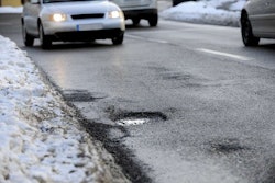
Such geocomposites may be placed directly beneath pavements, under aggregate base courses, used as a capillary break in northern states to stop development of ice “lenses” and subsequent potholes, in embankment and dike drainage areas with high water tables, as an alternate to granular blanket drains, and with channel drains.
Geosynthetics and Bridges
Geosynthetics also are used in designs for accelerated bridge construction. For example, the Geosynthetic Reinforced Soil Integrated Bridge System (GRS-IBS) was initially developed by FHWA as part of its Bridge of the Future initiative in 2002. The success of GRS-IBS technology demonstrations in Ohio and New York shows this component of the “bridge of the future” has merit.
FHWA’s GRS-IBS implementation guide (Google FHWA-HRT-11-026) takes an engineer through the site selection, design, and construction process. Also available is a companion document, Geosynthetic Reinforced Soil Integrated Bridge System Synthesis Report (FHWA-HRT-11-027), which substantiates the design method and presents case histories for GRS-IBS bridges.
“GRS-IBS can be built at a lower cost, with faster construction and improved performance, and can be used to build single span bridges on all types of roads,” said FHWA’s Jennifer Nicks. “This method of bridge support blends the roadway into the superstructure to create a jointless interface between the bridge and the approach roadways.” Compared to standard bridge construction, transportation agencies that use GRS-IBS can cut their costs by 25 to 60 percent, FHWA says.
GRS-IBS consists of three main components: the reinforced soil foundation (RSF), abutment, and integrated approach. The RSF is composed of granular fill material that is compacted and encapsulated with a geotextile fabric.
Use of the geotextile provides embedment and increases the bearing width of the GRS abutment. The abutment, meanwhile, uses alternating layers of compacted fill and closely spaced geosynthetic reinforcement to provide support for the bridge, which can be placed directly on the abutment without the need for a joint or cast-in-place concrete.
Construction of the abutment is relatively easy, involving a row of facing blocks, followed by a layer of compacted granular fill, and then a layer of geosynthetic reinforcement. This process is repeated until the required abutment height is reached.
For the third component of the system, GRS is used to construct an integrated approach road to the bridge, alleviating the common “bump” caused by differential settlement between bridge abutments and approach roadways.
The section on construction walks users through each step of the process, including labor and equipment requirements, site preparation, compaction, reinforcement, placement of the superstructure, approach integration, and site drainage.
Also featured in the guide is a design example for the Bowman Road Bridge in Defiance County, Ohio. The design example outlines the project process, including establishing the project requirements, performing a site evaluation, determining the layout of GRS-IBS, calculating loads, conducting both internal and external stability analyses, and implementing design details.
Read more in the May Road Science article in Better Roads.