For the contractors who invest in them, GPS/GNSS systems can deliver huge gains in earthmoving productivity, accuracy and speed. But because these are electronic and digital products, and because full blown GPS/GNSS systems for automated blade control can cost $60,000 to $100,000 per machine, many contractors have not taken the leap.
If the complexity of these systems has you sitting on the sidelines, or if you just need a refresher in the technology, this series of articles on GPS/GNSS 101 is for you.
For our introduction to the basics, we asked David Hilbig, Southwest regional sales manager for construction at Topcon Positioning Systems, to explain how the components of a GPS/GNSS system work together. In future articles we’ll go into more depth on how to set up excavators, dozers and motor graders with GPS/GNSS machine control and we’ll finish the series talking about how to integrate this technology into a site-wide control system.
How does GPS/GNSS work?
In simple terms, these systems receive the same satellite positioning signals you get on your car or smartphone map and navigation systems. The big difference is that systems designed for survey and earthmoving operations receive broadcasted radio corrections from on-site GPS base stations to make it highly accurate for rovers or machines in the field.
The rovers use this information to check or survey a site without the need for stakes in the ground. The machines use the information to cut, fill or dig to a profile that exactly matches the X-Y-Z coordinates on a digital topographic plan. This eliminates the majority of the survey staking that a site needs and the wait times that often accompany resurveys.
An operator in a machine that is GPS/GNSS guided has two options. In the “indicate” mode, he sees the final contours of the site on the digital plan on the screen in his cab and manually adjusts the elevation and slope of the blade to match the plan. In the “automatic” mode, the machine’s hydraulics take over the blade and automatically make those adjustments.
Partner Insights
Information to advance your business from industry suppliers
In addition to eliminating most of the staking chores, GPS/GNSS makes less skilled operators more efficient. And it can prevent operators from overcutting a pass and having to move the dirt multiple times to achieve final grade.
Satellite evolution
There’s a bit of digital magic involved in making this all work, which we will explain, but to avoid confusion, let’s start by defining some terms. You’ll often see this technology referred to as GPS or GNSS or as we put it, GPS/GNSS. What’s the difference?
In the early days, the only satellites available to beam this positioning information down from space were global positioning satellites, or GPS, put into space by the United States government. In the early 2000s, access to the Russian Satellite Constellation, Glonass, became available. Europeans have plans to complete their own series of satellites called Galileo. This combination of satellite constellations created the Global Navigation Satellite Systems or GNSS. Today, people use the terms GPS and GNSS somewhat interchangeably.
The base station
At the heart of any GPS/GNSS system is the base station. Via antennae, it receives the positioning signals from satellites orbiting the earth. But because these signals travel a great distance through the atmosphere, their accuracy tends to be in the +/- 30-feet range. Good enough for automobiles or airplanes, but not civil engineering.
The key to a base station is that it is set up precisely over a known, surveyed point. As the satellite’s signal travels though the atmosphere, there is an error in its position when received on earth. Since the base station knows precisely where it is located, it can determine the error. The error experienced at the base station is also seen by the rovers. The base station broadcasts this “differential correction” across the jobsite to all available man and machine rovers. The corrected signal is referred to as real time kinematic or RTK. This improves the accuracy to within millimeter tolerances, says Hilbig.
This base station broadcast is typically delivered through a radio signal. Where radio transmissions are problematic, however, the RTK transmission can also be accomplished via cellular modem.
A good analogy for the base station is the construction laser, says Hilbig. “Like a laser on a tripod, it can broadcast to an infinite number of receivers or multiple end users on the site,” he says. “But with GPS, you can cover huge elevation changes and great distances depending on terrain, and you don’t have to move it like you do a laser. Depending on the radio type and terrain you can often cover a three-mile radius.”
As mentioned, for a base station to function properly it must be set up over a control point or a known survey point. To do this, many contractors will mount it to a jobsite trailer or put it on a 4×4 post anchored in concrete in the ground, Hilbig says. On top of the post they’ll typically mount a threaded bolt so that crews can remove the unit for safekeeping at the end of the day and reinstall it the following day.
“The main thing you want to do when you set up the base station is to make sure you have an unobstructed view of the sky,” Hilbig says. The better the access to clear sky, the more satellite signals the unit can receive and the more accurate the data is. “The man-rovers and machine rovers may have to work up close to buildings or the tree line, which can limit their access to satellites.”
Today’s base stations are integrated systems with a GPS receiver, GPS antenna, a radio (or cellular) modem to send out the RTK signal, and a power source – typically a battery pack.
Rovers and machines
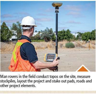
There are two types of rovers in the GPS/GNSS earthmoving world. A man rover is used to conduct topos on the site, measure stockpiles, layout the project, and stake out pads, roads, etc., during excavation. These have a GPS/GNSS receiver on the top of the pole, a radio antenna to pick up the RTK corrected signal from the base station, and then a controller or data collector containing the 3D model or digital terrain model.
The 3D model is created by the contractor or a consultant showing all the elements of the job: design surface, alignments, linework showing pads, roadways, curb and gutter, utilities, etc., as well as point files. All files incorporate the coordinate system used by the local surveyor.
The man rover is used to calibrate or localize the GPS to the established coordinate system. Surveyed control points, typically placed on the perimeter of the jobsite, are occupied by a man-rover for about two minutes to create a relationship between GPS coordinates (latitude, longitude, ellipsoid height) and the surveyor coordinates (northing, easting and elevation). This is a one-time operation performed on the first day of the job.
Machines act just like rovers except their GPS/GNSS antennae are mounted on masts attached to the blade of a dozer or motor grader and a control box is mounted within the cab to serve as the users’ interphase. On excavators, the GPS antennas are located near the counterweight.
Changes in technology
GPS-based earthmoving got its start around 2002. Since then, a number of changes and refinements have made it more practical and efficient.
One of those changes is the emergence in some areas of cellular reference stations. A cellular reference station performs the same functions as a local base station but eliminates the need for the contractor to own or set up a base station on his site. These reference stations broadcast their RTK information via cellular modem rather than radio signals.
Anyone within cellular reach of the reference station can tap into the signal and get accurate positioning information. Government sponsored reference stations typically require you to apply for permission to use it. There are also privately run reference stations that charge a fee for use.
The local dealers who sell GPS/GNSS equipment can help you find these services, and many of the dealers operate their own networks.
No more masts
Recently we’ve seen the emergence of the “mast-less” GPS/GNSS systems on machines. Instead of the tall masts sticking up on both ends of the blade of the machine, these newer systems use one or two inertial measurement units (IMUs) attached to the body of the machine.
The IMUs employ sensors, machine dimensions and gyroscopes that measure the pitch, roll and yaw of the machine. That spatial information along with the known dimensions of the machine enable the system to figure out exactly where the cutting edge of the blade is at all times. The machine gets its RTK signals from a low-profile antenna mounted on top of the cab (instead of receivers on a mast) and then the IMUs and software coordinate that information with the exact X-Y-Z position of the blade relative to the design surface. “Dual IMUs can talk to each other 100 times a second and give us an even better response and quicker reaction,” Hilbig says.